logic
A logic circuit the reader operates. It is written as a flowchart is, as what connects to what — parts, and the wires between them — and arranged by the environment along direction:, its implicit attribute, right by default. Every wire carries a level, 0 or 1, and is drawn by it: lit in the high: hue at 1, grey at 0, dashed while it is unknown. The reader flips a switch by clicking it, and the gates answer a gate delay apart, so a change is seen travelling through the circuit and a latch is seen settling. A cue sets a switch by keyframing its value:, so the prose can say "now set " and the circuit does. Each step shows the author's state: the switches as the cues have set them, and anything that remembers — a latch built from gates, a flipflop — as the cues so far have left it. The reader's own flips last until the step changes. A circuit that never settles, such as a latch released from both inputs at once, says so, and its loop's levels are unknown.
logic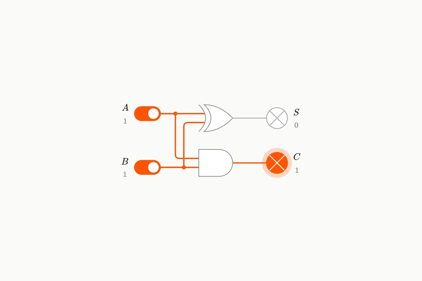
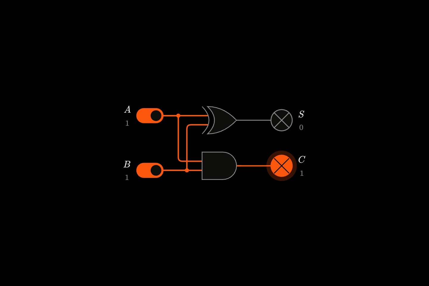
#The logic environment
logic draws a logic circuit that runs. It is arranged the way a flowchart is, from what connects to what, along direction: — its implicit attribute, right unless written — so logic:down{…} runs top to bottom. Every wire carries a level, and the reader changes the levels by clicking the switches.
#Parts and wires
Levels start at a switch or a clock, pass through gates, a mux or a flipflop, and end at a lamp. An alu is drawn for a datapath and computes nothing. A wire joins one part's output to another's input: wire(from: #a; to: #g). A gate's kind is its implicit attribute, and a gate has no words, so it is written with an empty body, gate#g:and{}.
A gate's inputs land on its back, as many ports as wires arrive, and its one output leaves its front and fans out to every wire that leaves it. Wires carry no arrowhead: the flow runs from switches to lamps, and a wire that runs back against it, into a latch's other gate, loops round the parts between.
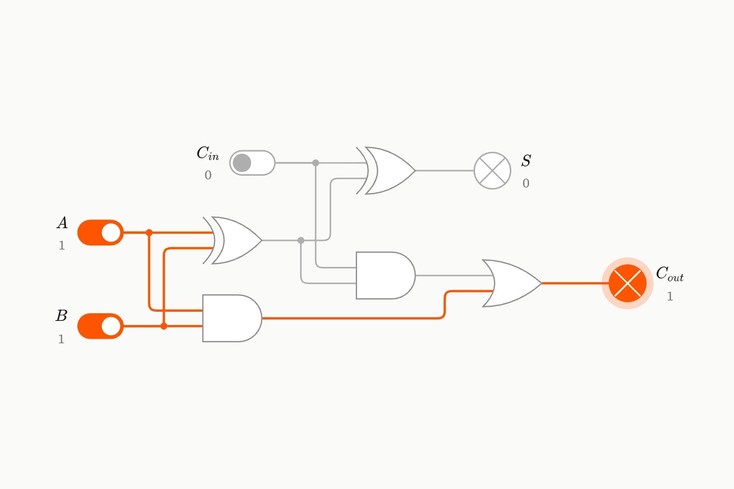
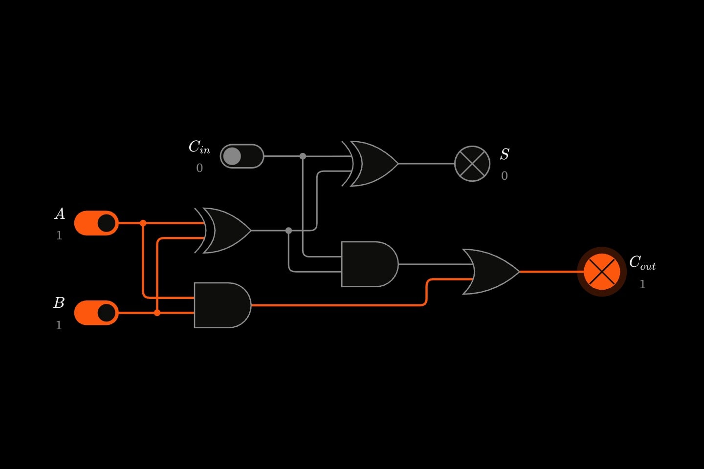
logic{
    switch#a{$A$}(value: 1)
    switch#b{$B$}(value: 1)
    switch#cin{$C_{in}$}
    gate#x1:xor{}
    gate#x2:xor{}
    gate#a1:and{}
    gate#a2:and{}
    gate#carry:or{}
    lamp#s{$S$}
    lamp#cout{$C_{out}$}

    wire(from: #a; to: #x1)
    wire(from: #b; to: #x1)
    wire(from: #x1; to: #x2)
    wire(from: #cin; to: #x2)
    wire(from: #a; to: #a1)
    wire(from: #b; to: #a1)
    wire(from: #x1; to: #a2)
    wire(from: #cin; to: #a2)
    wire(from: #a1; to: #carry)
    wire(from: #a2; to: #carry)
    wire(from: #x2; to: #s)
    wire(from: #carry; to: #cout)
}#Naming a port
A gate's inputs are interchangeable, so they are dealt in the order the wires are written. A multiplexer's and a flip-flop's are not, and a wire names the one it means after the part's id, as a column rides a dataset: to: #m.select, to: #ff.clock, from: #ff.qbar. A multiplexer's data inputs are d0, d1, … on its back, numbered from the top, and its select line is select (or s0, with s1 for a 4-to-1), which enters its side. A flip-flop takes d and clock and gives q and qbar. A wire that names no port takes the part's next free one.
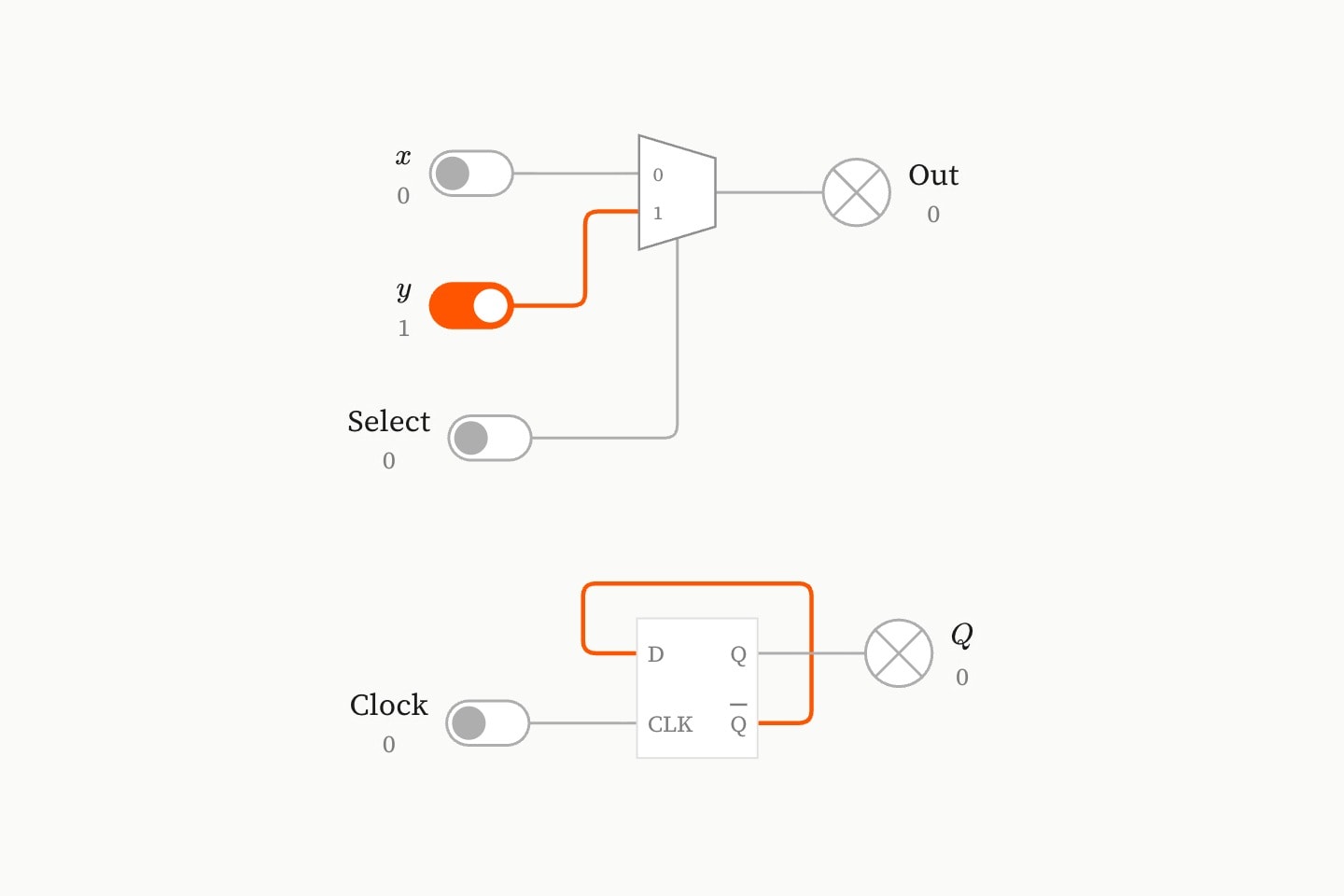
logic{
    switch#x{$x$}
    switch#y{$y$}(value: 1)
    switch#sel{Select}
    switch#clk{Clock}
    mux#m{}
    flipflop#ff{}(value: 0)
    lamp#out{Out}
    lamp#q{$Q$}

    wire(from: #x; to: #m)
    wire(from: #y; to: #m)
    wire(from: #sel; to: #m.select)
    wire(from: #m; to: #out)
    wire(from: #clk; to: #ff.clock)
    wire(from: #ff.qbar; to: #ff.d)
    wire(from: #ff.q; to: #q)
}#Levels, and a gate delay
A level is 0, 1 or unknown. A wire at 1 is lit in the environment's high: hue, orange unless written; at 0 it is grey; unknown, it is dashed. A switch is drawn as a toggle, its knob over to the right and its track lit when it is on, and a lamp as a circle crossed through, glowing when it is lit. Each writes its level beside its symbol, a question mark while unknown, so neither depends on colour alone. Every part publishes its level for the prose as level, so {{#cout.level}} reads the carry and follows it as the reader flips switches.
Each gate answers a change one gate delay after it, and all of them at once, so a change is seen travelling through the circuit a gate at a time. An unknown spreads only as far as it must: an AND with a 0 among its inputs is 0 whatever the others are, and an OR with a 1 is 1.
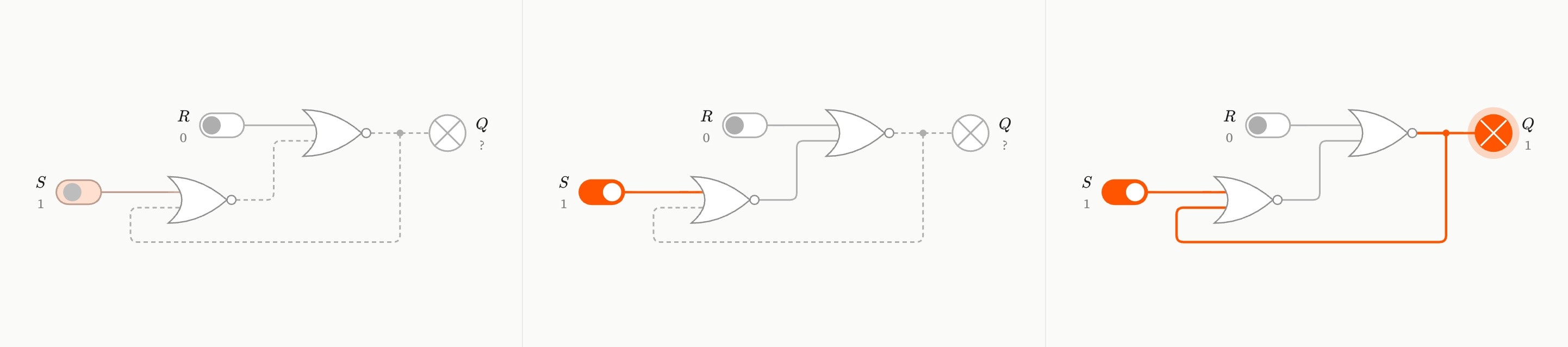
logic{
    switch#s{$S$}(value: 0 !cue.to{1}(at: 1))
    switch#r{$R$}
    gate#n1:nor{}
    gate#n2:nor{}
    lamp#q{$Q$}

    wire(from: #r; to: #n1)
    wire(from: #n2; to: #n1)
    wire(from: #s; to: #n2)
    wire(from: #n1; to: #n2)
    wire(from: #n1; to: #q)
}#Switches, cues and the reader
A switch's value: is where it starts, and a !cue.to on it flips it at a step, so the prose can say "now set S" and the circuit does:
switch#s{$S$}(value: 0 !cue.to{1}(at: 1) !cue.to{0}(at: 2))Each step shows the author's state. The switches stand where the cues have put them, and anything that remembers is in the state the cues so far have left it, replayed in the order they fired, whether the reader arrived by playing forward, stepping back or jumping. The reader's own flips last until the step changes. fixed keeps the reader's hands off a switch only the prose should move.
#Circuits that remember
Gates whose outputs feed back into one another can hold a state, and a latch built from them powers up unknown, as a real one does, until something sets or resets it. A gate's value: is the level its output starts at, for a latch that must power up in a known state. Changes the cues make at the same moment land together, so a latch released from both inputs at once races: if its levels are still changing after the circuit has had time to settle, the circuit says so and shows them unknown.
#Flip-flops and clocks
A flipflop takes the level at d on each rising edge of clock and holds it until the next; its value: is the level q starts at. A clock is a switch that flips itself, a square wave with period: from one rising edge to the next, ticking while the circuit is on screen. The reader pauses and restarts it by clicking it, and a cue starts or stops it through running:. For a clock the reader steps by hand, use a switch.
logic{
    clock#clk{Clock}(period: 2s)
    flipflop#ff{}(value: 0)
    lamp#q{$Q$}
    wire(from: #clk; to: #ff.clock)
    wire(from: #ff.qbar; to: #ff.d)
    wire(from: #ff.q; to: #q)
}
The circuits pack has the standard circuits ready-built — half and full adders, a 4-bit ripple-carry adder, a decoder, the SR and D latches and a ripple counter — each wired into a circuit through the ids of the parts that feed it, and read through the ids it names after its own name:.
@use:circuits

logic{
    switch#a{$A$}
    switch#b{$B$}
    switch#cin{$C_{in}$}
    circuits.full-adder(name: fa; a: a; b: b; carry-in: cin)
    lamp#s{$S$}
    wire(from: #fa-sum; to: #s)
}#Attributes
directionright (the default), left, down or up. A circuit too long for the environment always wraps the way lines of text do, each line starting again at the beginning, never snaking back, which would turn half its gates round; the strictly- forms are accepted and draw the same.downuprightleftstrictly-downstrictly-upstrictly-rightstrictly-leftlogic:valuerighttitlehighcolour: overrides it for that lamp.bluelight-bluedark-blueredlight-reddark-redorangelight-orangedark-orangeyellowlight-yellowdark-yellowteallight-tealdark-tealgreenlight-greendark-greenpinklight-pinkdark-pinkpurplelight-purpledark-purplegreylight-greydark-greyneutralhex(…)rgb(…)orangefocus#id naming a part. Animatable with !cue.to; absent, the frame centres.logic-anchorzoom!cue.to; absent, the circuit fits the environment.interactivefalsecontinuecontinue: #that-environment. The reader's explored camera carries forward; the switches start where this environment's own value:s put them.#Allowed content
#Allowed in
#Examples
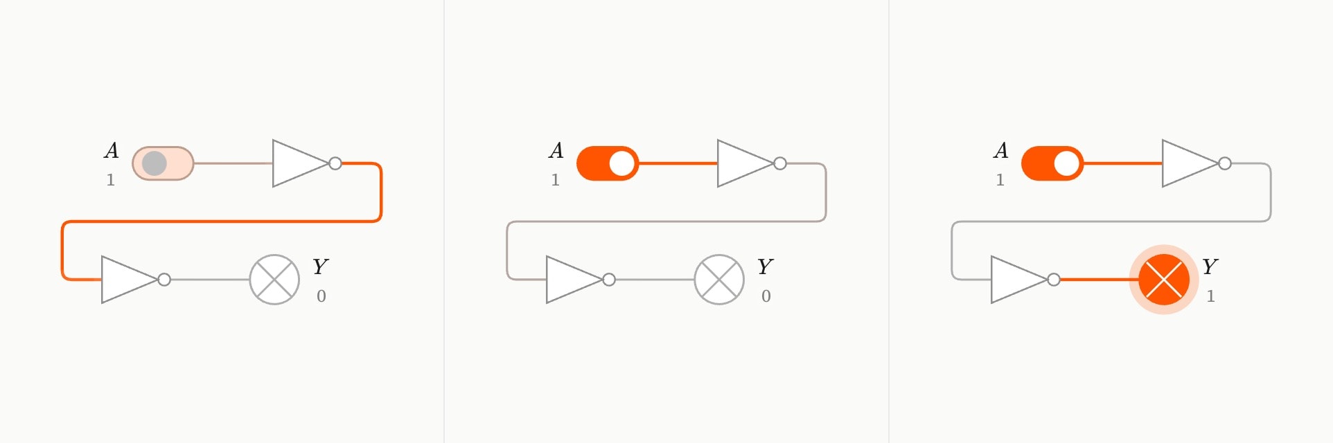
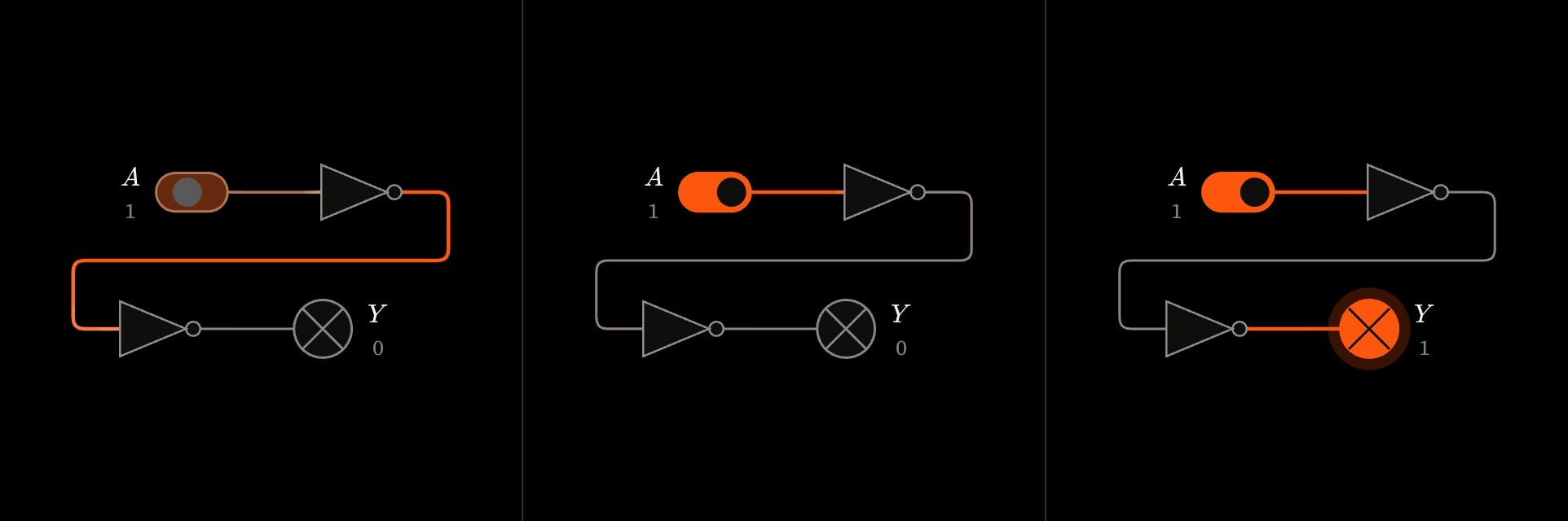
logic{
    switch#a{$A$}(value: 0 !cue.to{1}(at: 1))
    gate#n1:not{}
    gate#n2:not{}
    lamp#y{$Y$}
    wire(from: #a; to: #n1)
    wire(from: #n1; to: #n2)
    wire(from: #n2; to: #y)
}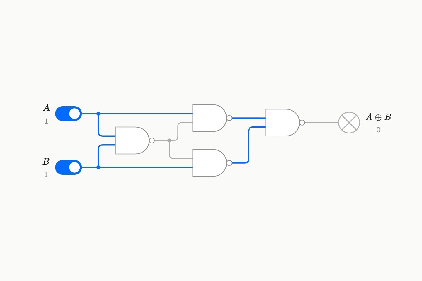
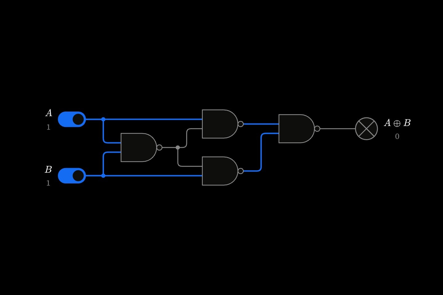
logic{
    switch#a{$A$}(value: 1)
    switch#b{$B$}(value: 1)
    gate#n1:nand{}
    gate#n2:nand{}
    gate#n3:nand{}
    gate#n4:nand{}
    lamp#y{$A \oplus B$}
    wire(from: #a; to: #n1)
    wire(from: #b; to: #n1)
    wire(from: #a; to: #n2)
    wire(from: #n1; to: #n2)
    wire(from: #n1; to: #n3)
    wire(from: #b; to: #n3)
    wire(from: #n2; to: #n4)
    wire(from: #n3; to: #n4)
    wire(from: #n4; to: #y)
}(
    high: blue
)