circuits

Import it with @use:circuits, then call its constructs under that name.
Pack
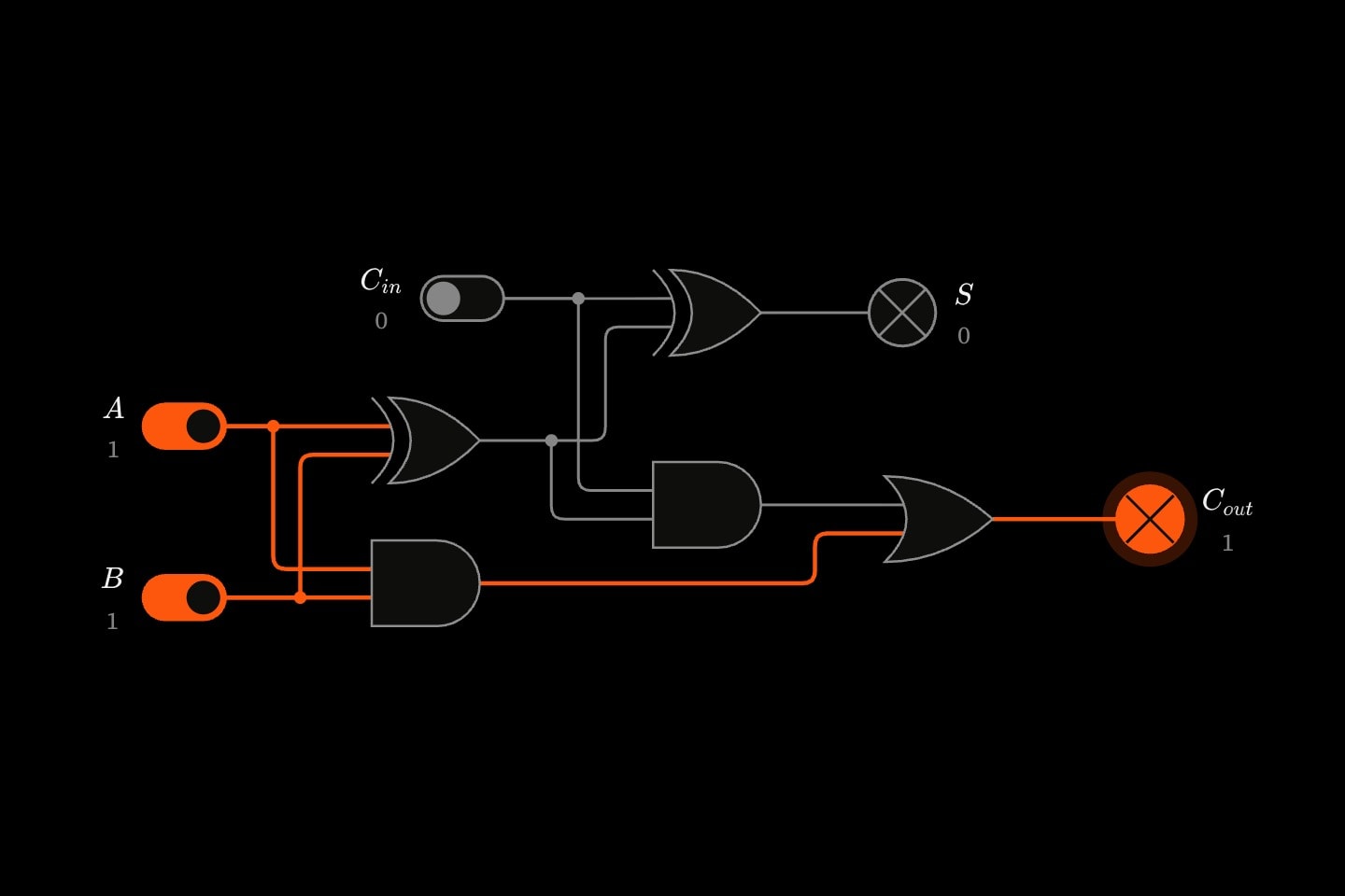
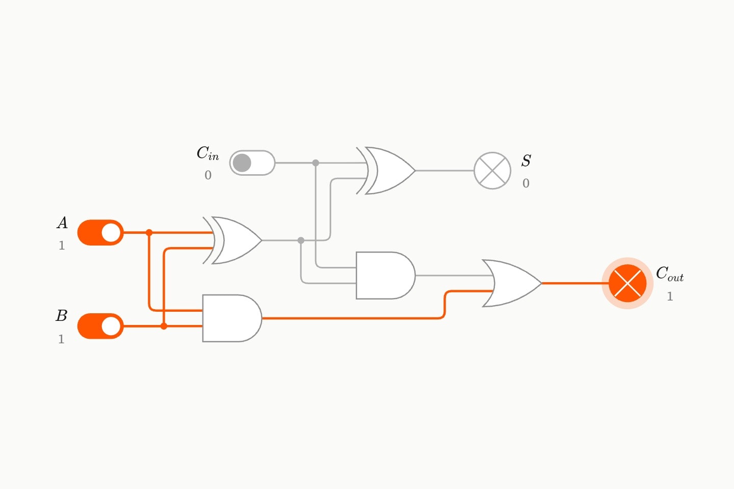
A full adder built from the pack, adding 1 + 1 + 0 with its carry lamp lit.A full adder built from the pack, adding 1 + 1 + 0 with its carry lamp lit.
@use:circuits

#Constructs

circuits.half-adder
A half adder: two bits in, their sum out as two bits. The sum A⊕BA \oplus B comes from an XOR and the carry ABAB from an AND. Its results are #<name>-sum and #<name>-carry.
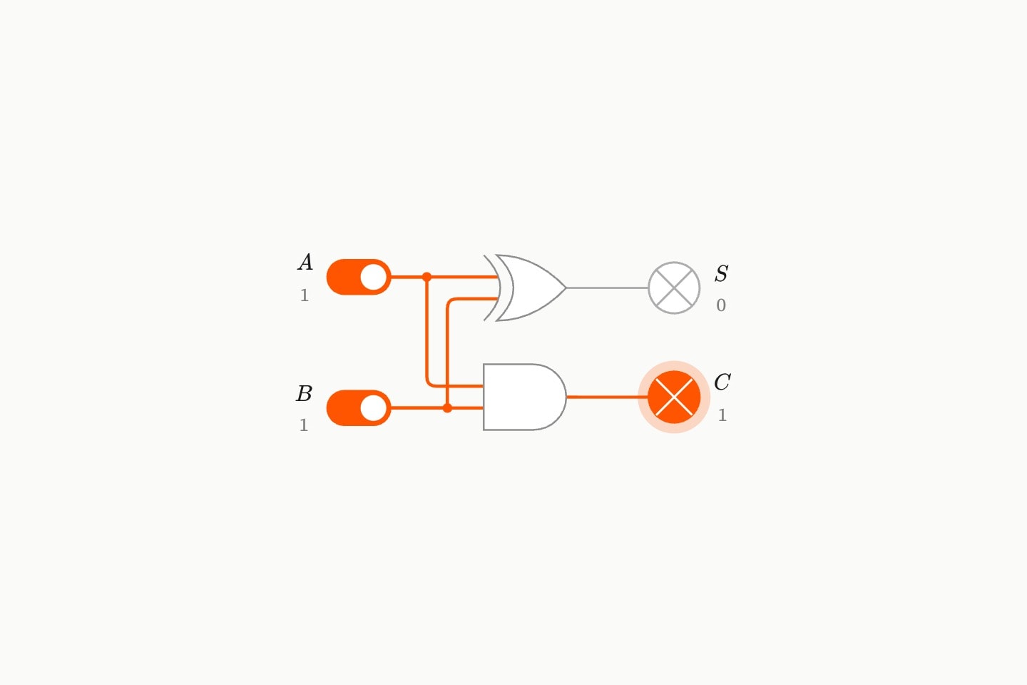
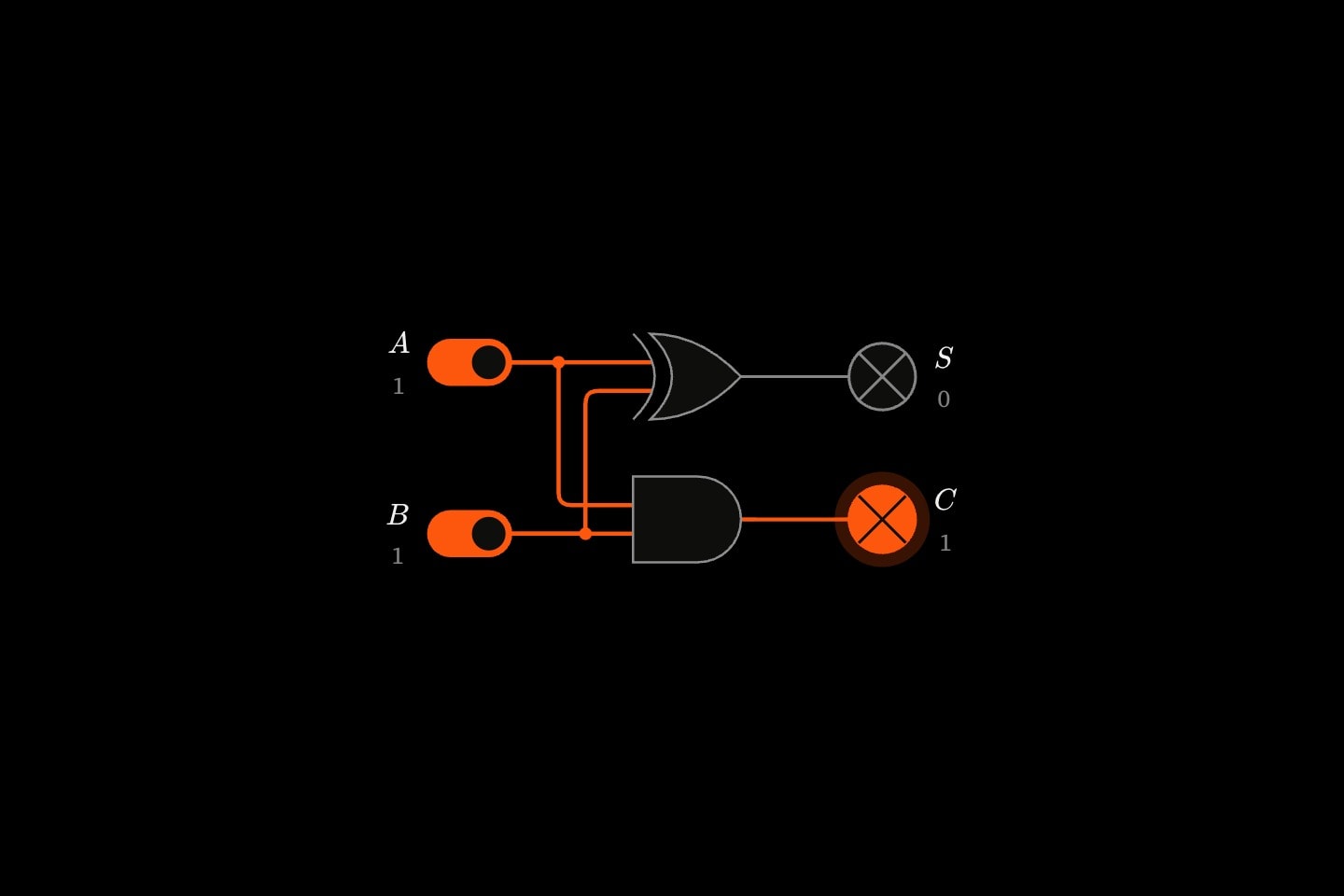
A half adder with both switches on: the XOR's sum lamp is dark and the AND's carry lamp is lit.A half adder with both switches on: the XOR's sum lamp is dark and the AND's carry lamp is lit.
nameRequired
The name its parts are known by: #<name>-sum and #<name>-carry.
aRequired
The part giving the first bit, by id: a, or ff.q for a port.
bRequired
The part giving the second bit, by id.
circuits.full-adder
A full adder: three bits in — two operand bits and a carry from the column to the right — and their sum out as two bits. The sum is A⊕B⊕CinA \oplus B \oplus C_{in}, from two XORs; the carry is AB+Cin(A⊕B)AB + C_{in}(A \oplus B), from two ANDs into an OR. Its results are #<name>-sum and #<name>-carry.
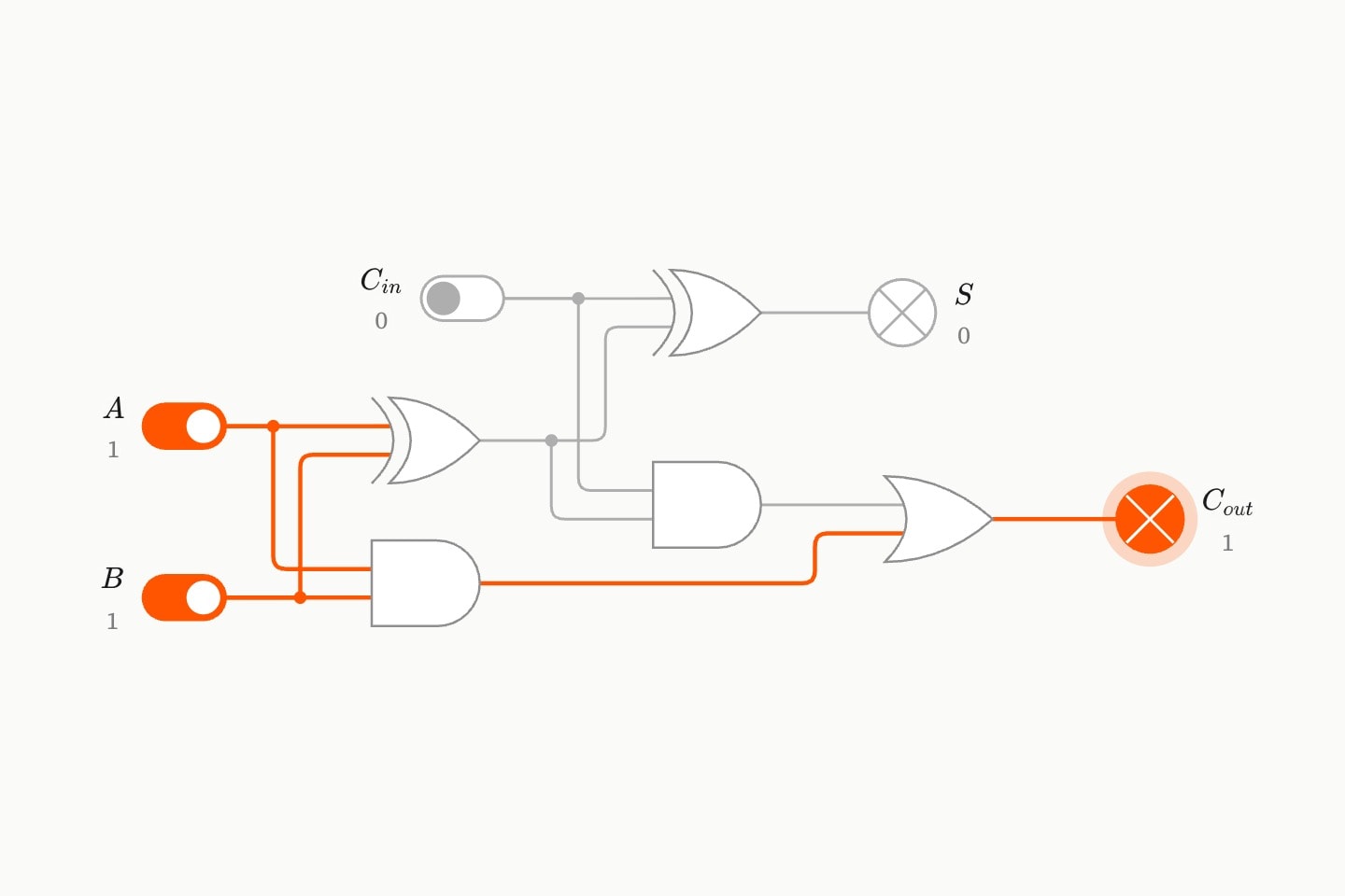
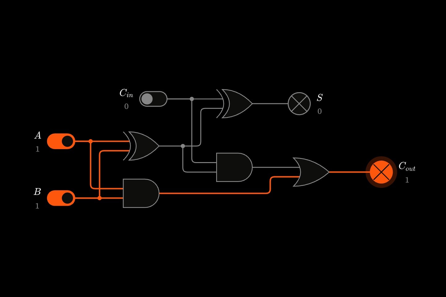
A full adder adding 1 + 1 + 0: two XOR gates make the sum, dark, and two ANDs into an OR make the carry, lit.A full adder adding 1 + 1 + 0: two XOR gates make the sum, dark, and two ANDs into an OR make the carry, lit.
nameRequired
The name its parts are known by: #<name>-sum and #<name>-carry.
aRequired
The part giving the first operand bit, by id.
bRequired
The part giving the second operand bit, by id.
carry-inRequired
The part giving the carry in, by id: a switch, or the carry out of the adder for the column to the right.
circuits.ripple-adder
A 4-bit ripple-carry adder: four full adders, each column's carry out wired into the next column's carry in, so a carry ripples from bit 0 to bit 3. It adds A3A2A1A0+B3B2B1B0+CinA_3A_2A_1A_0 + B_3B_2B_1B_0 + C_{in}. Its results are #<name>-0-sum to #<name>-3-sum, bit 0 first, and the carry out #<name>-3-carry.
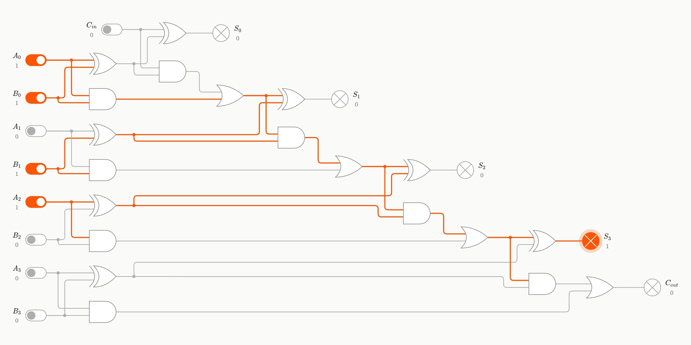
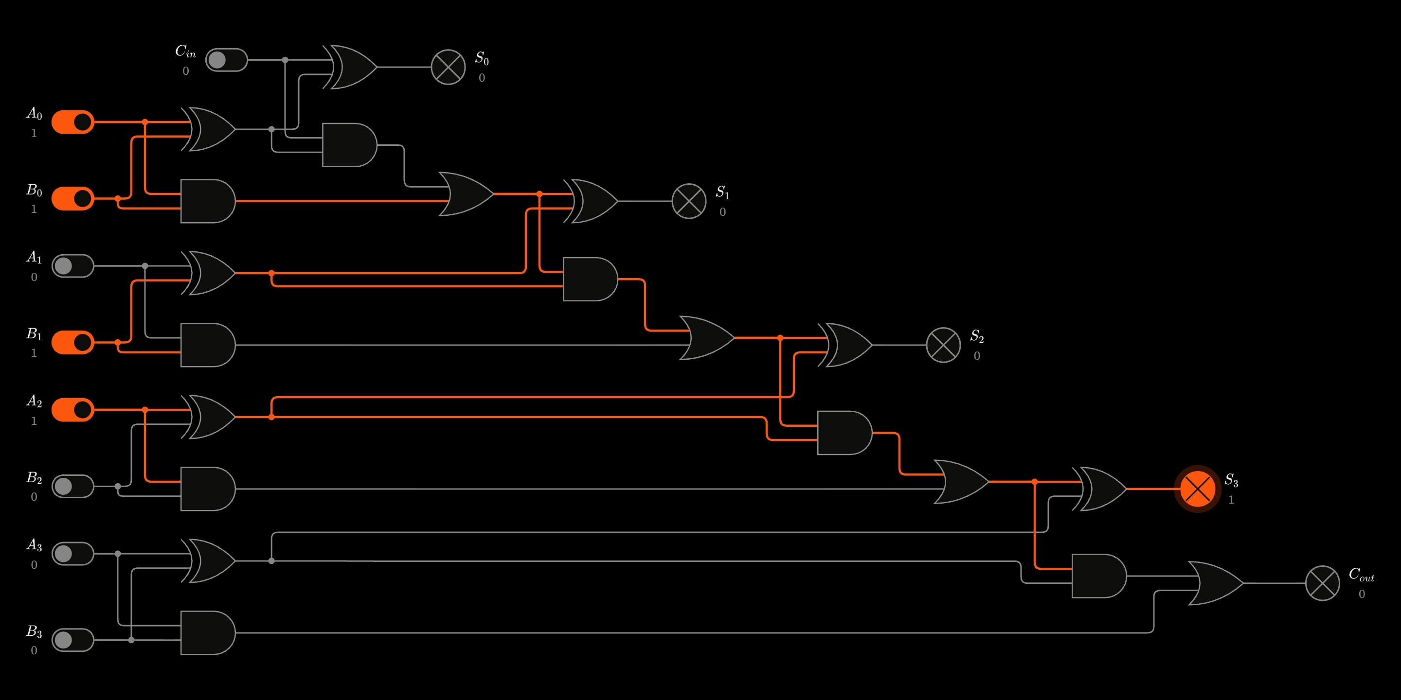
A 4-bit ripple-carry adder adding 0101 and 0011: four full adders chained by their carries, with only the sum lamp for bit 3 lit, giving 1000.A 4-bit ripple-carry adder adding 0101 and 0011: four full adders chained by their carries, with only the sum lamp for bit 3 lit, giving 1000.
nameRequired
The name its parts are known by: #<name>-0-sum … #<name>-3-sum and #<name>-3-carry.
a0Required
The parts giving AA's bits, by id, bit 0 the least significant.
a1Required
a2Required
a3Required
b0Required
The parts giving BB's bits, by id.
b1Required
b2Required
b3Required
carry-inRequired
The part giving the carry into bit 0, by id.
circuits.xor-from-nand
XOR built from four NAND gates — the classic proof that NAND alone can build any circuit. The first NAND's output feeds the two beside it, and their outputs meet at the last. Its result is #<name>.
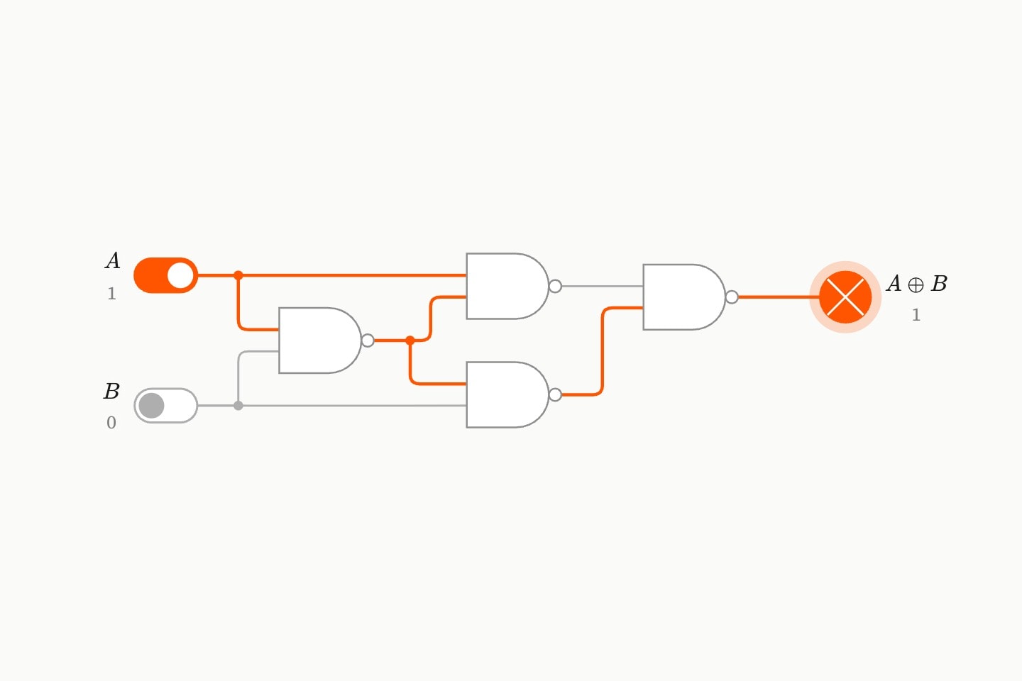
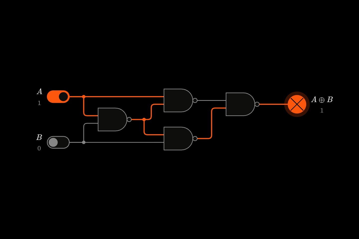
Four NAND gates wired as an XOR, with A on and B off, so the output lamp is lit.Four NAND gates wired as an XOR, with A on and B off, so the output lamp is lit.
nameRequired
The name of the last gate, whose output is A⊕BA \oplus B. The others are #<name>-first, -upper and -lower.
aRequired
The part giving AA, by id.
bRequired
The part giving BB, by id.
circuits.decoder
A 2-to-4 decoder: a two-bit number in, and exactly one of four outputs at 1 — the one it names. Two NOTs and four ANDs, one AND for each pattern of the two bits. Its results are #<name>-0 to #<name>-3.
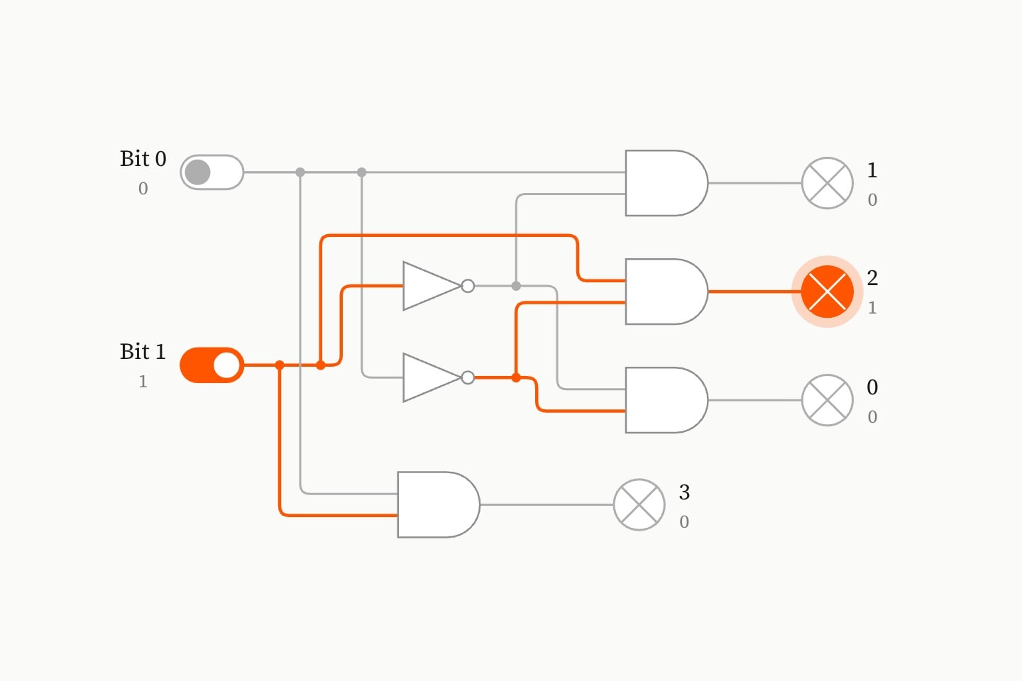
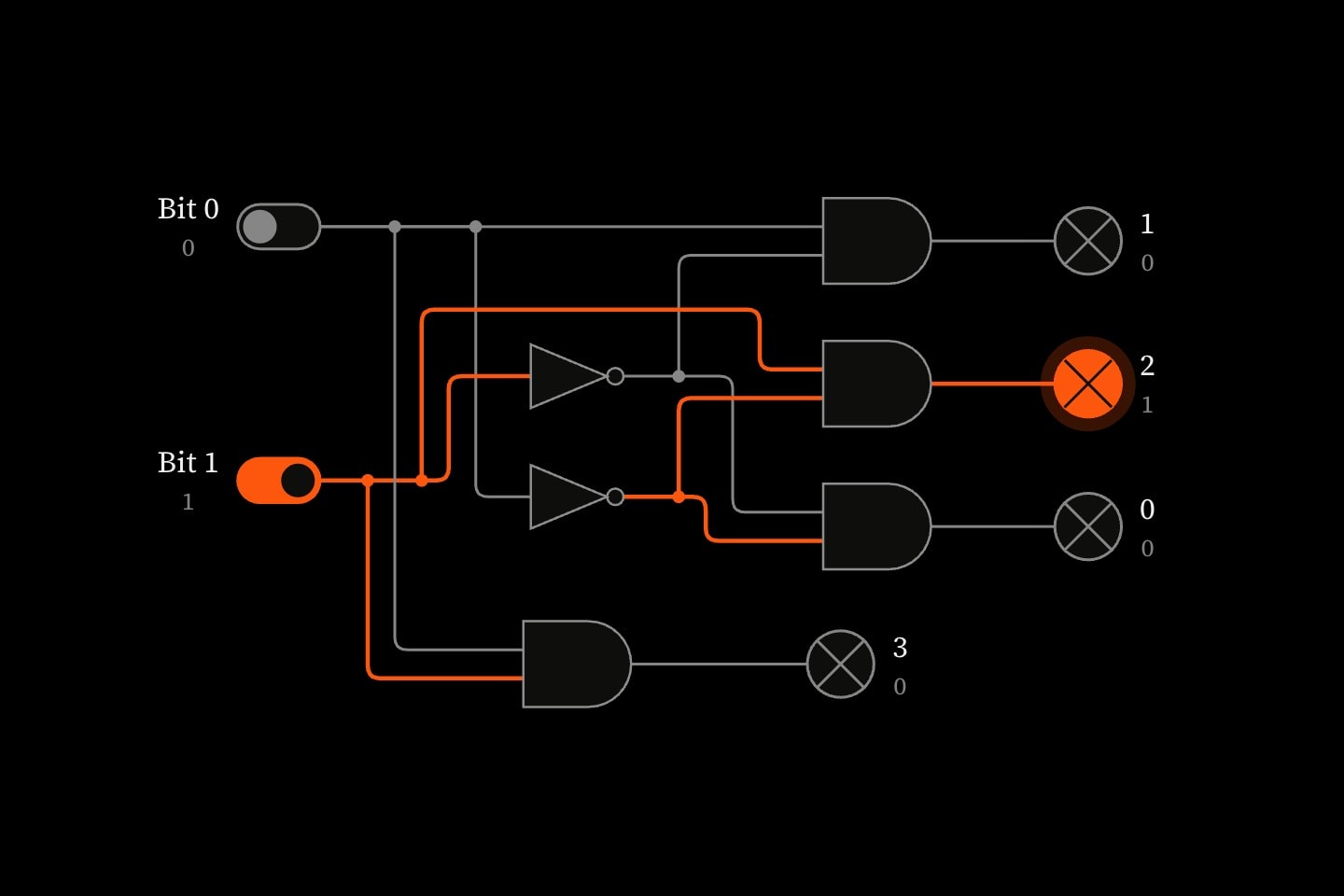
A 2-to-4 decoder given the number 10: of its four AND gates, only the one for 2 lights its lamp.A 2-to-4 decoder given the number 10: of its four AND gates, only the one for 2 lights its lamp.
nameRequired
The name its outputs are known by: #<name>-0 … #<name>-3, one for each number.
bit0Required
The part giving the low bit of the number, by id.
bit1Required
The part giving the high bit, by id.
circuits.sr-latch
An SR latch from two NOR gates, each one's output fed into the other's input. Raising set makes Q=1Q = 1, raising reset makes Q=0Q = 0, and with both low the loop holds what it was last told. It powers up unknown, as a real one does. Its results are #<name>-q and #<name>-qbar.
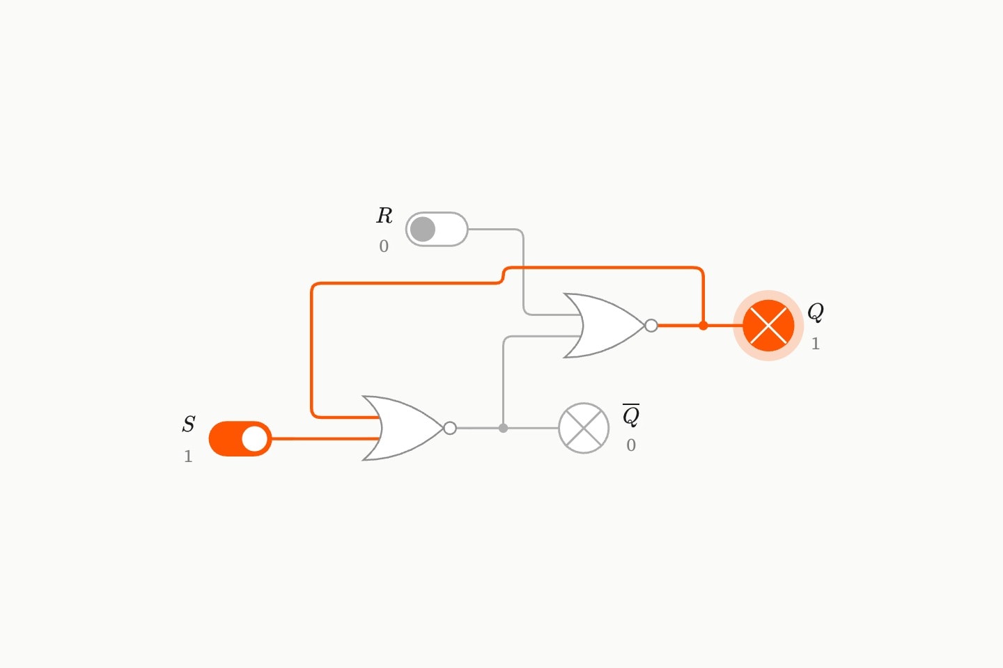
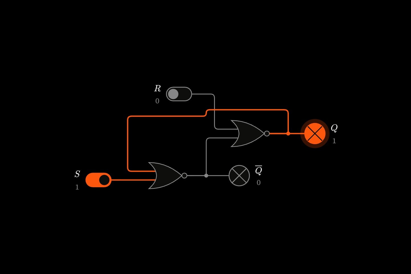
An SR latch from two cross-coupled NOR gates with set on: Q is lit and Q-bar is dark.An SR latch from two cross-coupled NOR gates with set on: Q is lit and Q-bar is dark.
nameRequired
The name its outputs are known by: #<name>-q and #<name>-qbar.
setRequired
The part giving the set input SS, by id.
resetRequired
The part giving the reset input RR, by id.
circuits.d-latch
A D latch: an SR latch with a gate in front, so it stores whatever is at d while enable is 1 and holds it while enable is 0. The ANDs make S=EN⋅DS = EN \cdot D and R=EN⋅D‾R = EN \cdot \overline{D}, so SS and RR are never both 1. Its results are #<name>-q and #<name>-qbar.

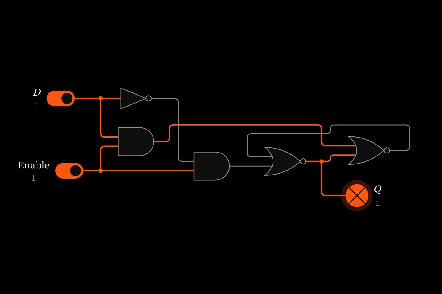
A D latch with data and enable on: a NOT and two AND gates in front of a NOR latch, its Q lamp lit.A D latch with data and enable on: a NOT and two AND gates in front of a NOR latch, its Q lamp lit.
nameRequired
The name its outputs are known by: #<name>-q and #<name>-qbar.
dRequired
The part giving the data DD, by id.
enableRequired
The part giving the enable, by id: a clock, or a switch.
circuits.ripple-counter
A 3-bit ripple counter: three D flip-flops, each with Q‾\overline{Q} fed back into its own DD so it toggles on every rising edge of its clock. The first is clocked by clock; each of the others by the Q‾\overline{Q} of the one before, which rises as that bit falls from 1 to 0 — so the three count up, 000000 to 111111 and round again. All three start at 0. Its results are #<name>-0 to #<name>-2, bit 0 first.
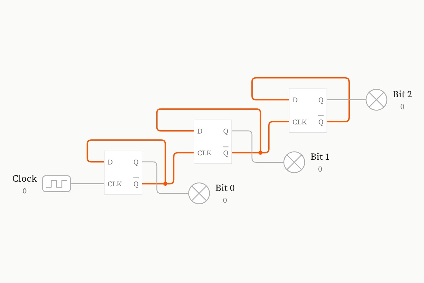
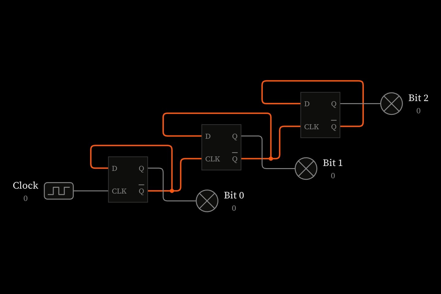
A 3-bit ripple counter: a clock into the first of three flip-flops, each flip-flop clocking the next from its Q-bar, with a lamp on each bit.A 3-bit ripple counter: a clock into the first of three flip-flops, each flip-flop clocking the next from its Q-bar, with a lamp on each bit.
nameRequired
The name its bits are known by: #<name>-0 … #<name>-2, bit 0 the least significant.
clockRequired
The part giving the clock, by id: a clock, or a switch the reader flips.

Last updated